Technically, it is impossible for ColourSpace to generate an inaccurate 3D Calibration LUT, as the ColourSpace Colour Engine will always generate the perfect LUT based on the profile used.
The only way that an incorrect LUT can be generated is if the profile data is incorrect/invalid, or if the application of the LUT is in some way at fault.
LUT verification is the only way to assess the accuracy of any calibration, and it is a critical process that needs to be fully understood, especially when the reported verification results show the calibration to be inaccurate. Where do the errors potentially reside, and why?
The information contained within this page will point out where LUT Calibration issues can reside, and how to understand their causes.
Calibration & Verification
The concept of verifying a calibration by running a second profile sequence should be rather obvious, and in simple terms makes perfect sense.
After calibrating the display, following the instructions in the 3D LUT Calibration guide, and the Hardware Integration specific User Guides as needed, any post-calibration verification process should then prove the accuracy of the final calibration. The performed calibration should compensate for any signal path errors, should it not?
Unfortunately, the answer is often no...
LUT Accuracy & Grey Scale
The first thing to realise is that ColourSpace cannot introduce any colour or grey scale errors into any generated LUT by its own actions/processing.
It is simply mathematically impossible.
The only way that any incorrect values can be added to any ColourSpace generated LUT is if the profile data is incorrect/invalid.
Such invalid/inaccurate measurements are obviously possible if the probe in use is not providing accurate readings throughout the volumetric display range, or the display itself is unstable, or if the TPG used is itself inaccurate.
Note: See Probe Accuracy for further information on potential probe induced profile errors.
Unfortunately, due to the understandable desire to assess grey scale as a separate entity to the full volumetric colour, such errors can be more easily visible, compared to the rest of the volumetric colours.
However, It must be remembered that there is no such thing as a grey scale as a separate entity compared to all other colours. All colour points are equally valid in all display calibration. Consequently, if there are invalid readings anywhere within the measured colour volume - not just the measured grey scale - the resulting calculated 3D LUT will contain inaccuracies.
Any LUT errors, regardless where they are located, will be due to original measurement/profiling errors, not generated by ColourSpace's colour engine.
This therefore means that when a calibration result appears to show any colour inaccuracies, in the grey scale, or anywhere within volumetric colour, the underlying profile data used to generate LUT will be the cause of such errors (assuming the application of the LUT is not at fault... which is also a possibility, as explained below).
The various sections within this user guide explains the possible issues that can cause a less than perfect calibration result.
If required, any specific issues showing in the grey scale can be managed by the use of Augment Data when generating a LUT; by using an alternative LUT Processing option, such as Hybrid; or via the use of the LUT Adjustment Filters, such as Axis Blend.
Generating a LUT using Peak Chroma, and then a second LUT using Hybrid, is a good method to assess if the profile data has invalid/incorrect measurements, as a profile that has no invalid/incorrect measurements will produce an identical LUT, as is shown in the following graphs.

The above profile is from a display that cannot make Rec709 gamut; is extremely non-linear, but additionally has been profiled using a Tristimulus with no Probe Matching to a Spectro, meaning the probe measurements are inaccurate to the actual colours being displayed on the display's screen, as defined in the Probe Accuracy user guide.
(Click the following graphs to directly compare them)


As can be seen, the 3D Volumetric LUT is largely identical, with mainly the Grey Scale 1D LUT component showing significant variations. This shows the profile data is in some way inaccurate/invalid, specifically the points surrounding the grey scale measurements.
Focused Patch Set
To gain the best possible grey scale calibration, the use of a Focused Patch Set is highly recommended - especially when the native grey scale (RGB Balance) is not close to the target white point.
Note: Focused Patch Sets are not specific to grey scale improvements, and will improve the full volumetric calibration.
Reduced Gamut Patch Set
Another approach for difficult displays is the use of Reduced Gamut Profiling, as the Colour Engine within ColourSpace does not require a full gamut range of patches.
Using a Reduced Gamut patch set focused the profile measurements into the central gamut of the display, where critical accuracy is more important.
Active LUT vs. LUT Upload
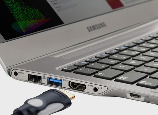
To understand potential Calibration & Verification Errors it is best to initially look at the simplest LUT verification workflow, using a display with internal LUT capability and profiling via a direct HDMI connection from the ColourSpace PC.
Direct HDMI Profiling
With a Direct Profiling configuration, the HDMI output from the ColourSpace PC is connected to the display's HDMI input, enabling direct profiling, as described in the HDMI User Guide.
It is also assumed the HDMI signal is RGB, and NOT YCbCr - see later!
In this profiling workflow the RGB triplet patch values, as defined by ColourSpace, are directly displayed on the monitor via the HDMI connection (assuming there are no active ICC profiles, or incorrect Graphics Card/Chip Set configurations, as defined in the HDMI User Guide), ensuring the values measured by the probe are as expected for the TPG triplet as defined by ColourSpace, and as accurate as the probe's inherent capabilities, and display stability.
Based on this direct profiling, the 3D calibration LUT generated will, in turn, be as accurate as it can be, based on the probe's reading accuracy, and the stability of the display.
Continue Active LUT vs. LUT Upload
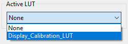
After LUT Generation, the first verification step is to run a profile using the Active LUT capability within ColourSpace.
The Active LUT capability effectively proves the underlying LUT calibration accuracy by passing the patch colour data through the LUT, before sending the patch to the display via the HDMI connection.
As a result, the patch colour displayed will have been corrected by the LUT, and the probe will read the new, corrected value, effectively proving the accuracy of the calibration.
The next step is to Upload the LUT into the display (as for this example the display has 3D LUT capability), and again re-profile.
Ideally, both verification profiles will match exactly, and the calibration will be perfectly accurate.
So, what could be wrong?
In this example, theoretically very little, as the workflows is very simple, assuming the instructions on the management of ICC profile and Graphics Card/Chip Set configurations have been performed correctly.
Even though the Active LUT and the actual LUT Upload into the display are in different location the simple RGB signal path minimises potential signal path issues.
The following shows the signal and profiling patch for the Active LUT.
ColourSpace Active LUT Verification
-

Patch Generation
Patch colour defined by ColourSpace, and sent to display as a HDMI RGB signal
-

Patch Generator
ColourSpace Test Patch Generator (TPG) located before the LUT
-

Active LUT
Active LUT held with ColourSpace, modifies the patch colour before sending to the display
-

HDMI Connection
HDMI RGB connection to the display
-

Display Measurement
Active LUT corrected patch colour displayed and measured on monitor
And the following shows the signal and profiling path when the LUT is uploaded directly into the display.
Display Uploaded LUT Verification
-
Patch Generation
Patch colour defined by ColourSpace, and sent to display as a HDMI RGB signal
-
Patch Generator
ColourSpace Test Patch Generator (TPG) located before the display, and the uploaded LUT
-
HDMI Connection
HDMI RGB connection to the display
-
Uploaded LUT
LUT uploaded into the display modifies the patch colour
-
Display Measurement
LUT corrected patch colour displayed and measured on monitor
As can be seen, there is theoretically little to go wrong, as the LUT should have the same effect on the signal when an Active LUT, and when Uploaded into the display. And as the signal profiling path is direct and simple, with little potential for unexpected distortion, the generated calibration LUT will be as accurate as possible.
If there are any differences between the two verifications, that points to some form of variation in the effect of the LUT when uploaded into the display vs. the Active LUT held within ColourSpace. Such variations could be LUT size (with the display Upload using a LUT size that is smaller than the internal ColourSpace size), or the need to apply a Video Scale process to the LUT before uploading if the display signal path is TV Legal, or can be down to poor signal processing within the display itself (or LUT Box, or software system using the LUT). It is LUT Processing issues that are the worse, as they cannot be corrected, as follows.
LUT Processing
LUT Processing errors are caused by poor signal processing within the display, LUT box, or graphics program, causing the output of LUT to be incorrect. A good example of this was the BMD HDLink Pro, which distorted any LUT loaded into it.
Unfortunately, some displays have similar issues.
The following shows just the grey scale (RGB Balance) results of the same calibration LUT verified within ColourSpace via Active LUT vs. the same LUT Uploaded into a display. As can be seen, the Uploaded LUT shows significant errors that are not present in the Active LUT verification.


The above comparison clearly shows that the LUT processing within the display is distorting the LUT calibration accuracy. While only RGB Balance is shown, similar errors will exist throughout the volumetric colour, and not just in the grey scale.
Unfortunately, such issues can only be overcome by the manufacturer correcting their image processing.
(While it may be possible to concatenate multiple LUTs, generated from multiple profiles with each LUT Uploaded, the results will never be ideal/accurate.)
The above assumes the TPG is accurate, as an inaccurate TPG will itself cause calibration issues - see the following.
TPG Processing
Another real potential for errors is the Test Patch Generator (TPG), as it is possible that any patch generator may interpret the RGB triplet patch values sent by ColourSpace incorrectly. Therefore the measurement values recorded by the probe would not match the correct calibrated values, and so provide inaccurate calibration, and inaccurate verification.
For example, this is true of the LG WOLED internal TPG, which is not bit-accurate to the sent triplet values, and also with many software TPGs that run on devices such as Chromecast, Shield, FireStick, Apple TV, etc. The accuracy can depend on the hardware device, or the software TPG used. For example, LightSpace Connect has proven to be accurate in many applications, while the Calman VirtualForge has not.
The following shows the basic similarity with display internal TPG, and 3rd party external TPG applications.
Display Internal TPG
-
Patch Generation
Patch colour defined by ColourSpace, and sent to display as RGB Triplet values via Network/USB connection
-
Data Connection
USB/Network data connection to the display
-
Patch Generator
Display Internal Test Patch Generator (TPG) located before the LUT
-
Uploaded LUT
LUT uploaded into the display modifies the patch colour as defined by the RGB Triplet colour data
-
Display Measurement
LUT corrected patch colour displayed and measured on monitor
3rd Party External TPG
-
Patch Generation
Patch colour defined by ColourSpace, and sent to external TPG as RGB Triplet values via Network/USB connection
-
Data Connection
USB/Network data connection to the external TPG
-
3rd Party External Patch Generator
3rd Party External Test Patch Generator (TPG) located before the display
-
Video Connection
Video connection from the TPG to the display
-
Uploaded LUT
LUT uploaded into the display modifies the patch colour as defined by the TPG
-
Display Measurement
LUT corrected patch colour displayed and measured on monitor
Depending on the location of the TPG, the potential for errors can stem from the display being YCbCr based, with errors in the conversion of the ColourSpace RGB Triplet patch values into YCbCr values for the TPG, and also within the re-conversion of the YCbCr values back into RGB before passing through the calibration LUT (as all 3D LUTs are RGB based) and then displayed on the display screen (again, as all display screens are RGB).
There can just as easily be issues with the TPG just not being accurate, and not displaying the ColourSpace defined Patch Triplet values correctly.


The above examples show an accurate External TPG vs. an inaccurate display Internal TPG, with both the low-light and high-light areas showing errors with the Internal TPG. The consequence is that any calibration LUT generated from the Internal TPG profile will not be accurate.
Signal Processing
Signal Processing issues are where the video processing distorts the image signal in an unexpected, and inaccurate way, and can cause serious problems if the image path is more complex, and uses a number of different hardware components.
This can be a serious issue with displays with Internal TPGs, as if there are any signal path distortions prior to the location of the TPG, the internal TPG patches will not compensate for the signal path, making any generated LUT inaccurate.
The issue with signal path processing errors is they can be difficult to spot, as an internal TPG positioned after the signal processing will not reveal any problems. An external TPG, that send the patches through the full signal path, is required to spot calibration issues.
Signal Path Image Processing Errors - Internal TPG
-
Patch Generation
Patch colour defined by ColourSpace, and sent to display as RGB Triplet values via Network/USB connection
-
Data Connection
USB/Network data connection to the display TPG
-

Signal Path Processing
Video electronics distorts normal image signal, but is bypassed by the TPG signal
-
Patch Generator
Display Internal Test Patch Generator (TPG) located after the signal processing
-
Uploaded LUT
LUT uploaded into the display modifies the patch colour as defined by the RGB Triplet colour data
-
Display Measurement
LUT corrected patch colour displayed and measured on monitor
In the above signal path the video processing electronics adds a distortion to any real image signal, before it reaches the screen.
(The video processing can be within the display, or any external video processing system within the signal path.)
As a workflow example, a skin tone colour with triplet value (145, 107, 113) is sent to the display. The video processing electronics distorts the triplet values to 146, 105, 114, and it is that value that is then displayed on the screen.
However, when ColourSpace sends a patch triplet value to the displays TPG of the same original value (145, 107, 113), that is the colour the TPG shows on the display screen, as it is not distorted by the video processing electronics.
Therefore, the Calibration LUT generated will be inaccurate, as it will not compensate for the distortion introduced by the video processing electronics.
The potential for such signal path issues is an extremely valid reason for an external TPG to always be used as the input to the whole signal path chain.
Signal Path Image Processing Errors - External TPG
-
Patch Generation
Patch colour defined by ColourSpace, and sent to external TPG as RGB Triplet values via Network/USB connection
-
Data Connection
USB/Network data connection to the display TPG
-
3rd Party External Patch Generator
External Test Patch Generator (TPG) located before the signal processing
(Could also be Direct HDMI TPG from ColourSpace PC) -
Video Connection
Video connection from the TPG to the display
-
Signal Path Processing
Video electronics distorts the TPG signal, as well as normal image signals
-
Uploaded LUT
LUT uploaded into the display modifies the patch colour as defined by the RGB Triplet colour data
-
Display Measurement
LUT corrected patch colour displayed and measured on monitor
In the above signal path the video processing electronics adds a distortion to both the patch colour, as well as any real image signal, before it reaches the screen.
(The video processing can be within the display, or any external video processing system within the signal path.)
As a workflow example, a skin tone patch with triplet value (145, 107, 113) is defined within ColourSpace, and sent to the display. The video processing electronics distorts the triplet values to 146, 105, 114, and it is that triplet value that is then displayed on the screen and is the resulting colour measured by the probe.
When ColourSpace generates a calibration LUT it will generate a correction within the LUT that corrects for the colour the display showed, which includes a correction for the distortion introduced by the video processing electronics.
However, the LUT correction will have a different result depending on where in the video path the LUT is then located...
If the LUT is positioned before the video processing electronics it will apply the correction to the signal in advance of the error being introduced. So, the 145, 107, 113 value will be come 144, 109, 112, and when this colour reaches the video processing electronics, the error introduced will most likely not be the same relative error as before, as the colour triplet value is NOT the same! So the LUT correction will now be wrong, as the introduced error will be different!
The LUT must be positioned AFTER the video processing electronics to correct the introduced errors.
Signal Delay
A very obvious, but easy to overlook issue is that of a signal delay from the ColourSpace PC to the actual display being calibrated, especially when the connection is not a simple direct HDMI connection.
Such a delay means the the patch being displayed on the monitor being calibrated actually occurs slightly after the patch displayed within ColourSpace. Therefore, unless the correct amount of Extra Delay is added, the probe will actually start reading before the correct patch is being displayed.
The same is true with displays that require settling time between patch changes, such as (W)OLEDs and FALD displays for example. With (W)OLEDs there can be colour memory, so the correct colour patch can take a while to settle, while FALD displays can initially fluctuate due to their backlight array dimming algorithms.

Any calibration or verification result is therefore going to be wildly incorrect, and should be simple to spot, as most of the graphs will show wildly inaccurate plots.
Built into ColourSpace is an Extra Delay option, to add the necessary delay into the initiation of each probe measurement to counter the signal path delay.
Auto Extra Delay
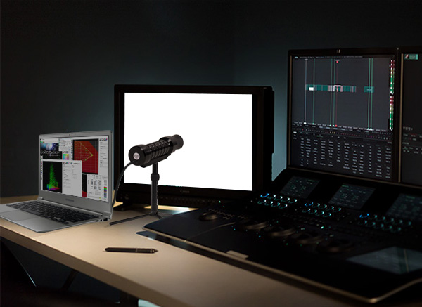
While there is an Auto option for Extra Delay, some probes will defeat the automated calculation of the required delay due to their in-built processing that attempts to discard invalid measurements, or average multiple readings. Such in-built processes cannot be overcome, and means the required Extra Delay will require visual verification of the delay, comparing the Floating Patch window within ColourSpace to the patch displayed on the monitor being profiled, as shown in the above image.
To have the best chance for an accurate Auto Extra Delay value, the probe should be set to a fast measurement time/low integration time, with no averaging/auto or similar processed active. If there are alternative measurement options, such as Frequency/Period/AIO for the i1D3, all available modes should be tested and the reported Delay values compared. It may also be necessary to try slightly slower integration times, again to get comparison values.
Obviously, if a probe's internal processing is discarding invalid measurements, or averaging them out, it means the probe is potentially providing valid readings. However, the potential for error due to patch contamination is still there, and a manual Extra Delay value should be entered to prevent possible measurement errors.
LUT Size
The LUT size (LUT Granularity) also has an impact of calibration accuracy, depending on the underlying display issues. Therefore displays or LUT boxes with small internal 3D LUT capability can potentially show different calibration accuracy when the ColourSpace LUT is uploaded.


For displays that have poor underlying volumetric colour variation, including grey scale, the difference will be less colour accuracy throughout, as above.
If the display has a stable, linear native response, the main variation will be the level of backlight contamination/colour error within the near black shadow range, due to the lower granularity of the 3D LUT.
Signal Range
The expected signal range for any given display - TV Legal/Extended/Data Range - can also cause calibration errors, if the correct range workflow is not applied.
Errors can be within the signal path, including any TPG in use, or the display itself, or Patch Scale setting within ColourSpace.


In the first graph the display has been profiled with a Data range signal, when the display expect a TV Legal range signal.
In the second graph the display has been profiled with a TV Legal range signal, when the display expect a Data range signal.
Comparing the two incorrect grey scale graphs it can be seen that when a display that expect a TV Legal range signal is profiled with a Data range signal, the grey scale is effectively compressed, with the lower (and potentially upper, depending on the display being Super White capable or not) areas showing repeated measurement values.
When a display that expect a Data range signal is profiled with a TV Legal range signal the grey scale is effectively stretched, with the lower and potentially upper areas being clipped, with the measured black being lifted, and peak white being reduced.
Gamut Coverage
Measuring gamut coverage, using just the peak chroma values, is not a good way to measure calibration accuracy, as greater peak chroma gamut coverage does not always equate to better accuracy.


The native display gamut suggests it can cover a fairly large percentage of the target Rec709 colour gamut, although the native white is cyan, with black being very blue.
Calibration with Gamut Mapping Disabled appears to show that a wide gamut coverage is possible, but note the peak green measurement is not correct, as it is off-axis with respect to the target colour space. The Green Hue is inaccurate.
Calibration with Gamut Mapping Enabled shows gamut coverage as being lower, but the peak green measurement is accurate with respect to the target colour space. The Hue is now correct.
(The small inaccuracy in the peak green hue plot is due to the way Gamut Mapping has to include some hue/saturation variation in the Out Of Gamut colours.)
When the No Gamut mapping result is plotted directly in comparison to the target colour space and with Gamut Mapping Enabled, the calibration inaccuracy in hue is obvious.
The assumption that is all to easy to make is that when calibrating with Gamut Mapping Enabled the area outside the peak primary gamut triangle is going to be cut off, and therefore drastically reduce the display's colour range.
This is not correct, as the gamut triangle is ONLY showing the values for the peak chroma values, not the gamut coverage for any other colours, and ColourSpace will calibrate each potential colour separately, maximising the total volumetric calibration of the display.

As can be seen, with Gamut Mapping Enabled, the full available gamut of the display is calibrated, not just the gamut with the peak RGB values.
Matrix vs. 3D LUT
The above Gamut Coverage information brings us to another often asked question, that while not really an error does impact the accuracy of calibration.
That question is what is the difference between a 3x3 Matrix (with or without a 1D LUT), compared to a 3D LUT calibration?
The above is a very good example of the difference, as a matrix calibration will not be able calibrate all available colours the display can accurately display, while a 3D LUT calibration will. A matrix calibration will clip the display gamut to the peak colours.

The clipping is due to a 3x3 matrix defining a six sided 3 dimensional shape, with flat sides, while a 3D LUT will map each and every input colour to a separate output colour, without constraint, meaning each individual colour can be calibrated without limitation or being restricted to peak primary colours - as the above Gamut Coverage section shows.
See Volumetric Errors and Quick Profiles for more information.
Volumetric Errors
A term used a lot within this website is Volumetric when describing the accuracy of any display calibration. But what exactly does this mean, and why is it so important, and why can a 3x3 matrix not manage volumetric errors, as stated above?
Basically, a display has volumetric issues if it shows non-linearity errors within its gamut - essentially, the output of the display is not linear and predictable when the input signal is changed in a linear and predictable way between zero and 100% signal range. Potentially 0% and 100% may be accurate, but any percentage value in-between will contain an error.
So, 0% Green (black!) can be accurate, and 100% green can be accurate, but 20%, 52%. 76%, etc., Green can easily be inaccurate.
And that is the issue with a 3x3 matrix - it can never correct those in-between errors, as it has no volumetric capability. A 3D LUT is required to correct such volumetric errors.
More information on Volumetric Issues can be found in the HDR Volumetric Accuracy section below.
Assessing displays for underlying Volumetric issues
With ColourSpace, spotting underlying Volumetric display issues is extremely simple, as any good display should map to itself when in an uncalibrated, native state.
After profiling a display, the Modify option within the Manage Space library can be used to Extract the native colour space from the profile.
When the profile is mapped to the extracted colour space and non-linear Volumetric issues will become obvious, as for a Perfect display, each graph would plot 100% correctly, with every measurement plotted green, with zero dE error.
Any graph plot that is not perfect shows underlying non-linear Volumetric issue.

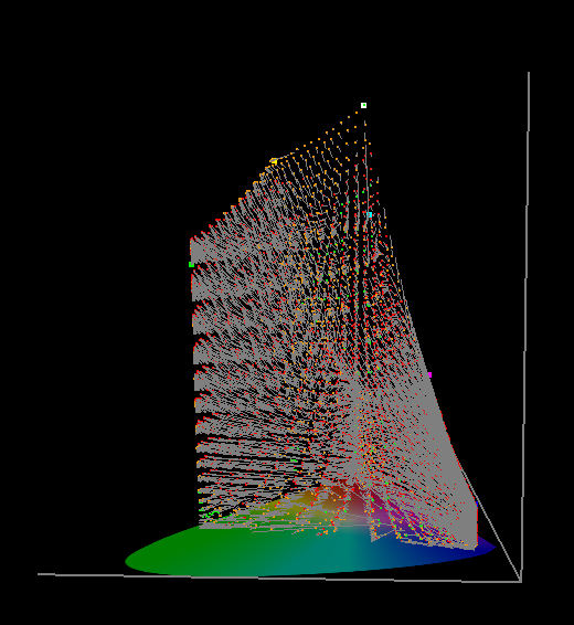
The above display profile, plotted against its own Extracted colour space, shows a range of Volumetric issues, with few measurements being green, and a very obvious bow/distortion in the blue to red gamut edge.

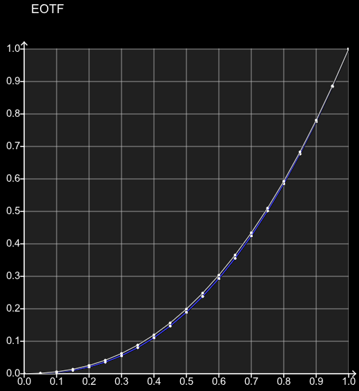
The EOTF plot shows few errors

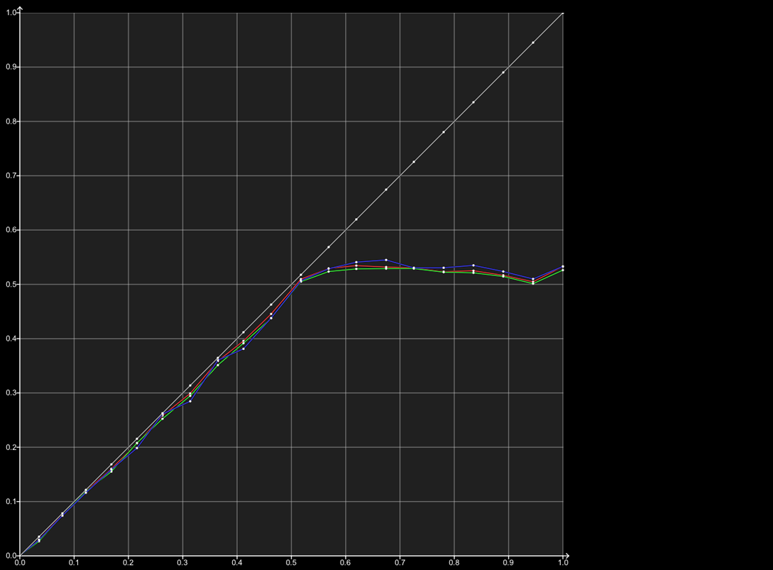
RGB Separation shows serious volumetric errors, with major cross-coupling and luma issues caused by the individual RGB channels not tracking the equivalent grey scale value, or inaccurate grey scale values vs. the equivalent RGB primary values.
The unique 3D volumetric graphs within ColourSpace helps further in understanding just what the underlying Volumetric issues are.


Toggle the above graphs to also show the Tangents applied.
See Matrix vs. 3D LUTs and Quick Profiles for more information.
LUT Scaling
LUT Scaling can also cause calibration issues when the LUT is uploaded in a display or LUT box.
The most obvious issue is when the 3D LUT within the display or LUT box uses a full-range cube, but the signal path is TV Legal, meaning that the LUT data needs to be scaled to match the TV Legal range within a data range LUT, using the ColourSpace Video Scale function.


If the LUT is not scaled correct, the gamut will be larger than target, assuming the display's native gamut is also larger than the target gamut, and the grey scale will show unexpected errors.


With the LUT correctly scaled, the gamut and grey scale match the correct targets, and also match a ColourSpace Active LUT verification.
Quick Profiles
ColourSpace includes two main profiling functions - full volumetric, often 3D Cube based, profiling, and the far faster Quick Profiling method. Both methods can produce excellent results, but with a great differences in profiling speed.
Using a Quick Profile (Grey Ramp, or Grey & Primary, etc.) to perform a display profile can be a very quick, and potentially can generate very accurate 3D LUT calibrations.
However, Quick Profile based calibration will only work accurately if the display has a very linear response to input signal changes, meaning it has no non-linear volumetric errors.
Note: A 3D LUT generated from a Quick Profile is effectively a 1D LUT and 3x3 Matrix, held within a 3D LUT, although if Secondary colour points are used within the Quick Profile patch set, the calibration results will better a 1D+Matrix calibration, as a unique Multi-primary colour engine will be used.
Quick Profiles can only be generated via Characterisation, and not via Manual Measure.
The RGB Separation graph is a good indicator of a display's linearity, or not, as RGB Separation compares each primary R, G, and B patch of the same stimulus value, matching the individual RGB patch measured values to the expected colour matrix combination for the equivalent grey patch. Any error in the graph shows the display is suffering colour decoupling issues with the display's separate RGB colour channels. This means that an input colour change that should affect only a single colour channel also causes changes within the other colour channels - what is known as cross-coupling between the colour channels.
Display's with such non-linear volumetric issues cannot be accurately calibrated with a 1D LUT and 3x3 matrix, and so cannot be accurately calibrated with a Quick Profile.
See Matrix vs. 3D LUTs and Volumetric Errors for more information.
Display Technologies
An obvious issue with different display technologies is Metameric Failure, as described within the Perceptual Colour Matching page.
However, there are other issues that are less obvious, but can cause image problems that can be very difficult to overcome.
As part of the assessment of display calibration ColourSpace has a unique self-verification capability, enabling any display to be assessed to itself, to better understand a given display's underlying capabilities and issues that will affect potential calibration accuracy.
This concept stems from a very simple premise, as any good display, when in its native and uncalibrated state, should effectively profile to itself very accurately.
To assess underlying issues with any display, clear/disable any/all calibration, and profile the display in its native state, and assess the profile matched to its own native colour space and gamut, which makes any volumetric issues simple to see.
Such Self-Verification is performed by extracting the display's native colour space from the profile using Extract Space.

Profiling a display to itself (to its own native gamut and gamma) really does show the underlying quality of any display...
Calibration Accuracy - Post Calibration
A question that is rarely asked, but in reality is critical for any display, is how well calibrated is the display AFTER calibration..?
Obviously, any display will drift in time, and so will require re-calibration, but that is not the question here. The question is: immediately after calibration, and after the calibration has been verified to be accurate, is the display now REALLY accurate when displaying real images/footage?
You may think this a stupid question, as the display has just been calibrated, and verified to be accurate...
But, when profiling and calibrating did you use any of the compensation options within ColourSpace? For example, did you use Drift, or more specifically the Stabilisation options?
If the answer is Yes, you must now realise that the display was only accurate because of the use of those options, and when playing real footage will not have the same corrections applied, and will immediately become uncalibrated.
This is especially true of displays that require the use of the Stabilisation option (although also true with Drift, to a lesser extent), as the insertion of black frames after each real calibration patch allows the display to cool, preventing thermal instability.
Obviously, when in real use, such displays will not have regular cooling periods, and will immediately suffer thermal instability, especially if the display is being used in a colour critical environment, such as for grading, as the same image/scene will be held on the display for extended periods, causing thermal instability as the display screen heats up.
This means displays that require the use of Stabilisation Patches for calibration should be treated with caution if being used in colour critical grading environments.
Probe Accuracy
It is fairly well understood that the probes used for calibration really do define the ultimate level of colour accuracy that can be attained.
And unfortunately, some probes are far worse than others.
The following shows a direct comparison between a well known monitor manufacturer's in-built probe, and an i1D3 using a Corr. File generated on the same monitor with a CR-250 4nm Spectro.

As can be seen, the error is significant.
The i1D3 and Corr. File has been chosen as the comparison, as that is the minimum most users should be using for basic level calibration, although as the Corr. File will not normally be generated on the actual monitor in use, there is still room for error, as the ? CORRELATION FILE ACCURACY modal window example shows within the i1Display Pro/Calibrite page.
Investing in good probes really is a necessity for colour accurate calibration.
See also the dedicated Probe Accuracy page.
Manual Adjustments - After Calibration
After performing a 3D LUT based calibration users can sometimes be tempted to tweak the display's manual controls. Such adjustments will always break the 3D LUT calibration, regardless of where in the display's image processing chain the controls exits.
There is an incorrect assumption that having the display's manual controls after the 3D LUT means they can be used post calibration, without affecting the accuracy of the 3D LUT calibration. That assumption is incorrect, as while not as bad as having the manual controls before the 3D LUT, altering controls post LUT will still break the calibration result.
The issue is that the 3D LUT is correcting any non-linear irregularities in both the display's image processing electronics, as well as the actual screen. Therefore making any changes either before or after the LUT will break the relationship between the correction the 3D LUT is generating, and the location of the errors within the display.
Manual Controls post-LUT
-
Input Signal
Input video signal
-

Input 1D pre-LUT
Input 3x 1D RGB LUT for gamma and colour temp
-
3D LUT
3D LUT calibration
-
Manual Controls
Display manual controls
-
1D post-LUT
1D LUT for screen linearity
(Often a single 1D gamma only LUT) -
Screen
Display screen
In the above signal path the issues are relatively obvious, as it is often assumed the screen has a purely linear response to input signal changes. But, that is not the case, as is defined by the need to often have an input 1D LUT to attempt to linearise the screen's response.
Regardless, changing the output from the 3D LUT via manual controls (brightness, contract, gain, etc) before the signal gets to the screen will break the final display calibration as the 3D LUT output (and the pre-1D LUT) expect the screen to be exactly as it was when profiled for LUT generation.
It should also be noted that if a display has a 3D LUT followed by a 1D LUT, the 1D LUT cannot be adjusted after the 3D LUT has been generated and uploaded. With a 1D LUT followed by a 3D LUT, the 3D LUT cannot be adjusted after the 1D LUT has been generated and uploaded.
Any post calibration signal path adjustments can only ever be at the beginning of the calibration chain, although even then unexpected results are likely!
BT1886
BT1886 can be a problem on displays with even slightly lifted blacks, due to the way it raises EOTF, especially in the shadow region. This causes the shadows to become washed-out, which in turn will cause the colourist to attempt to grade the shadows darker. When the graded footage is then viewed on a display with a standard power law gamma, or a display with a lower black and calibrated to BT1886, the shadows will appear crushed.
This can be seen in the following images, showing the target gamma for a display with a 0.01 nit black level, and 100 nits peak white. The lift in the shadows can clearly be seen.
(The blue plot represents a Rec709 power law 2.4 EOTF)


This can be seen in more detail in the following graph, which shows the BT1886 Gamma (blue plot) as a differential plot compared to a 2.4 power law gamma (the Zero line).
Note: The first and last points have no valid gamma value, so have been omitted.

As can be seen, as the curve heads towards black the gamma value decreases, lifting the brightness.
(As the graph is a differential graph, it shows the variation from the target EOFT, which is Rec709 2.4)
Pre-Calibration Issues
Before any LUT based calibration is attempted, all displays should be pre-set to disable any internal calibration processing, as well as to set desired black/white levels, without clipping and crushing.
The need to disable any internal colour processing is to ensure the display is set to its maximum gamut, without processing based artefacts or colour distortions, as such issues will often not be correctable with later 3D LUT based calibration.
For most displays, such a pre-setup will leave the display in the best possible state for accurate calibration.
However, some displays have inherent issues that no amount of pre-setup can alleviate, and are usually due to the display having active internal colour management that cannot be disabled. The issue may be down to the display being forced into a pre-set colour space, such as P3 or Rec2020, or having poor colour management that causes bad RGB Separation issues.
The following show just such an issue with a JVC projector when placed into wide gamut mode, as the projector is mapped into the selected colour space, which cannot be disabled to allow the display's underlying native gamut response to be used with the wide gamut filter wheel in place.
The following shows a JVC projector with obvious inherent volumetric issues, due to the application of an internal Rec2020 colour space preset, which cannot be disabled.


The above CIE charts show the basic problem with any in-built calibration, when the native gamut of the display is lower than the target colour space. The area within the Rec2020 colour space that is outside of the projector's actual achievable gamut is mapped back to the display's gamut edge. This can bee seen in the second chart, where error Tangent lines have been added to define the colour accuracy errors.
Note: There are a lot of inaccurate calibration errors within the projector's available gamut, as shown by the Red measured points and the Tangent Error lines, and these are the errors we are attempting to calibrate out via the use of an external 3D LUT.
The result with the gamut drop-off between the display's available gamut and the target Rec2020 is having multiple input colours all being mapped to the same output colour at the gamut edge. This is the real issue with the display, as secondary calibration will struggle to 'undo' having multiple input colours all mapping to the same output colour.
Note: Such gamut issues, caused by displays having in-built calibration that can't be disabled, can affect many different displays/projectors. The example here is just an example of the issues. Many JVC projectors cannot have internal calibration disabled when in wide gamut mode, but can have different colour spaces selected, so potentially lessening the gamut drop-off.
This is why being able to turn off any internal display colour management is critical for accurate re-calibration. It is exceptionally difficult to calibrate accurately on-top of an existing calibration, especially when the in-built calibration is to a sub-set of the larger target colour space.
If the display cannot be pre-set to a better level of pre-calibration set-up (basically any in-built calibration disabled), calibration can still be performed using ColourSpace through the use of a Reduced Gamut Patch Set, Focused Patch Set, or via the Sub-Space option, potentially combined with LUT Concatenation.
See: Sub-Space, Reduced Gamut Profiling specifically the Bad Pre-calibrated Displays section, and Focused Patch Sets.
HDR Volumetric Accuracy
The accuracy of HDR displays is something of a difficult area for many to assess, as the existing metrics used to define calibration accuracy are just not capable of showing true volumetric issues.
To explain this, see the following examples generated with ColourSpace. Both displays are HDR, with a Peak Luma of around 700 nits to 800 nits.
In these charts we have adopted the self-profile approach, enabling a better understanding of a given display's underlying capabilities and issues that will affect potential calibration accuracy. Self Profiling also enables any display to be directly compared to any other display as a direct relative comparison.
This concept stems from a very simple premise - any good display, when in its native, uncalibrated state, should effectively profile to itself very accurately.
Therefore, measuring the RGB primaries, and white point, for any display, and generating a target colour space with those values, a full volumetric profile of the display should map each and every measurement accurately to the target colour space.
The 3D charts below are also have colour coded measurement points, with the default being Green showing points that have a sub-1 dE, Orange showing points are between 1 and 2.3 dE, and Red showing points are above 2.3 dE.
The dE Threshold values can additionally be user defined.


In the above 3D CIE graphs the LCD display shows a relatively good/acceptable level of underlying display volumetric capability, while the WOLED graph shows issues throughout, that become increasingly worse as display brightness increases, caused by the addition of the White pixel.


The second set of graphs have dE Tangent lines included, which show the dE error for each and every point, making the difference a lot more obvious. As can be seen, the issue is both Gamut reduction (desaturation), and a drop in brightness/luminance as the displayed colour attempts to increase in saturation.
The direction of the tangent/error lines defines the issue, with vertical lines signifying a luminance error.


Using the unique normalised 3D CIE Cube graphs of ColourSpace it becomes a lot easier to visualise the volumetric issue with any display. The WOLED graph shows just how much volumetric accuracy is missing.


And again, adding dE Tangent lines helps highlight the errors.
Note: When a single point is selected, all other Tangent lines will be dimmed. Setting a colour value that has not been measured will make all Tangent lines bright.

The last RGB Separation graphs really simplify displaying the issue. As brightness increases the WOLED RGB gamut can't maintain an equal level of brightness with the grey scale (Luma), and clips harshly well before the peak luma of the display.
As can be seen, the LCD is ok, while not perfect, but the WOLED has major issues that are easily apparent, due to the inclusion of the white pixel, as this distorts the standard RGB colour channel relationship - excessively as brightness increases.
Standard RGB OLED displays work well for SDR use, requiring no additional white pixel. Adding the white pixel cause volumetric issues throughout the whole brightness range (including SDR), and causes serious issues with HDR. While the SDR issues can be calibrated out with a high-density 3D LUT via an external LUT box, the HDR issues cannot.
In very simple terms, this means that WOLEDs can never be accurately calibrated for HDR, due to a lack of colour volume...